the most findamental latch is simple SR latch or SR flip flop, where S & R stand for set & reset. It can be constructed with the help of latch and two more NAND gates.
the symbol of S-R flip flop
the truth table for the same is :-
S
R
Q
0
0
no change
0
1
0 (reset)
1
0
1 (set)
1
1
not valid
Case 1 - S = 0 , R = 1
S = 0 , R = 1 , Q = 0
S = 0 , R = 1 , Q = 0
LET S = 0 , R = 1 , Q = 0
When S = 0, the output of gate G-3 = 1.
When R = 1, the output of gate G-4 = 0.
Therefore, both inputs of gate G-2 are (0, 0), which makes Q' = 1.
Now, both inputs of gate G-1 are (1, 1), which makes Q = 0.
Hence, this case gives stable outputs as Q = 0 and Q' = 1.
Clocked S-R Flip-Flop
It is often required to set or reset the memory cell in synchronism with a train of pulses known as clock (CLK).
If a clock input is added to a S-R flip flop , then a clocked S-R flip-flop is obtained.
symbol of clocked S-R flip-flop
the truth table for clocked S-R flip flopis :-
S
R
Q
0
0
no change
0
1
0 (reset state)
1
0
1 (set state)
1
1
forbidden
Application of S-R flip flop
they are very simple and basic.
they are simple but are not used much because of their forbidden state where (S=R=1)
they are mainly used in switching circuits , as they provide simple and efficient switching function between set and reset states
S-R flip flops are used to eliminate mechanical bounce of switches in digital circuits . when mechanical switches are pressed or released , they often take some time and vibrate several times before setting down .this non ideal behaviour of the switch is called switch bounce or mechanical bounce . By using a clocked S-R flip flop in such switches the switch will come to use only after an recieving a clock pulse signal
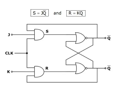
J-K flip-flop
The uncertainity in the state of S-R flip flop when S=R=1 can be eliminated by conveting it into a J-K flip flop . it is an imp memory element that behaves like SR flip flop except in the situation where S=R=1 . J-K flip flop is the improved version of S-R flip flop. the S=R=1 state of S-R flip flop is converted to toggling state in J-K flip flop. JK means Jack Kilby , a texas instrument engineer who invented IC(intergrated circuits )
Two additional AND gates are ussed with S-R flip flop to design J-K flip flop. the data inputs of J-K and ANDed with Q & Q' respectively to obtain i.e. S =J. Q' and R = K.Q. A clock signal is passed to both the AND gates for synchronizing i.e. enabling and disabling the flipflop operation.
When J = K = 0 => S = R = 0 irrespective of the value of Q & Q' . this results in both zero as input to the next part of the circuit (i.e. SR flipflop part of the JK flipflop ).The flip flop will retain its last output value with no change.
the truth table for clocked J-K flip flop is :-
S
R
Q
0
0
no change
0
1
0 (reset state)
1
0
1 (set state)
1
1
toggle
Application of S-R flip flop
JK flipflop is most widely used type of flip flop, it is considered as universal flipflop
it is used as a main component for designing :-
counters
registers
sequence detector
frequency divider
Race around condition of jk flip flop
The difficulty of both inputs 1 being not allowed in an S-R flip flop is eliminated in a J-K flipflop by using feedback connection from outputs to inputs of the gates G-3 and G-4. The The J=K=1 state is called toggling output state or uncontrolled changing i.e. a racing condition in JK flip flop truth table for JK flip flop assumes that the inputs do not change during the clock pulse (CK master=1), which is not true beacuse of the feedback connections.
A more practical method for overcoming the difficulty (to satisfy the inequality of small propoation delays in integrated circuits by using edge triggering rather than level triggering ), if the flip flop is made to toggle over one clock period . This approach leads to the use of the master-slave configuration .
Master - slave flip flop
A master slave jk flip flop is a cascade of two S-R flip flops with feedback from the outputs of the second to the inputs of the first.
so the first is called master and second is called slave. Positive clock pulses are applied to the first flip flop.
If J=K=0 there will be no change in the output value.- When the clock = 0 , the master will be inactice and so the saleve becomes active.
if J=K=0 there will be no change in the output value
if J=0 & K=1, the output will be reset state
J=1 & K=0, the output will be set state
if J=K=1 the output toggles
the truth table for the same is :-
CK
J
K
Q
1
0
0
Qn
1
0
1
0 (reset)
1
1
0
1 (set)
1
1
1
Qn'
D Type flip flop
The Delay type flip - flop can be contructed using either S-R flip flop ,J K flip flop or master slave flip flop. It has only one input referred to as D- type or data input. However , an invertor is attached between two inputs of flip flop i.e. both the inputs of flipflop cannot be same.
By using a NOT gate between the two inputs of SR flip flop , we can set or reset the flip flop by using single input only. D type flip flop can receive complemented inputs only , as two inputs are connected by a NOT gate.
Truth Table for D-Type Flip-Flop
D
Q
0
0
1
1
T type flip flop
In a J-K flip-flop, if J = K, the resulting flip-flop is referred to as a T-type flip-flop. It has only one input, referred to as T-input. If T = 1, it acts as a toggle switch. For every clock pulse, the output Q changes.
T
Qn +1
0
1
Qn
Qn'
When T=0, J=0, K=0 hence the output and the input remain the same. When T = 1, then J=1, K=1, output is complement of the input i.e. it toggles. That is why it is called a toggles (T) flip flop.